Explanatory notes on NOE
Design Calculation App
for NOE H 20 deck formwork edge and intermediate primary beams
The calculation equations
are based on the design loads in EN 12812:
Formwork weight g
= 0.35 kN/m²
Live load: v = 0.75
kN/m²
Concrete load b=
25 x d kN/m²
Concrete surcharge p
= 0.1 x b kN/m²
0.75
≤ p ≤ 1.75 kN/m²
Total load q=
g + v + b + p
Bending deflection formwork l/500 in
acc. with EN 12812
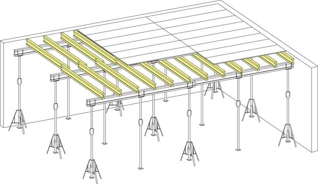
❶ Boarding support beam
❷ Edge primary beam SR
❸ Intermediate primary beam SM
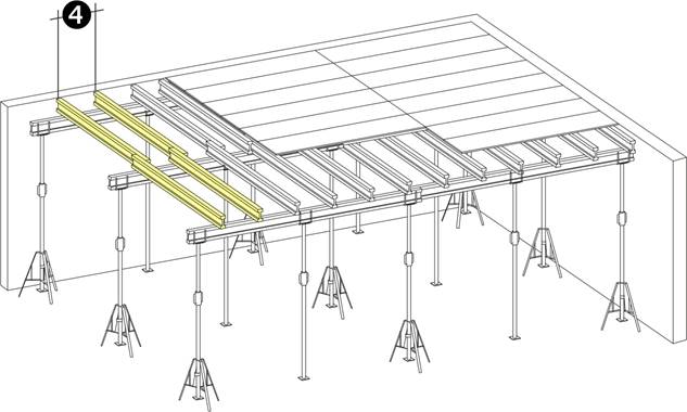
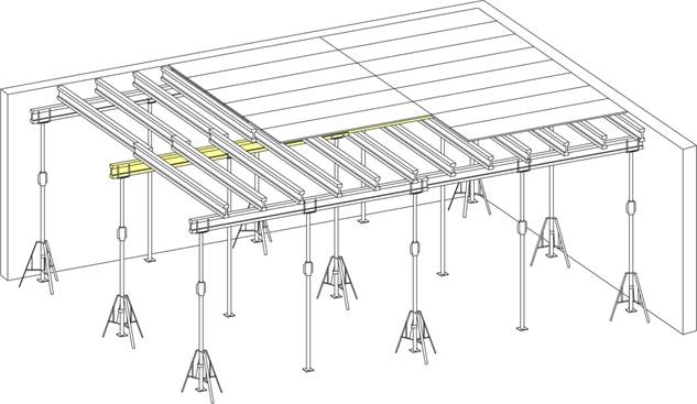
❹ Boarding support beam spacing a
Assuming the use of 22
mm three-ply panels supported transversely to the fibre direction.
The maximum permissible primary beam spacing must be observed.
Maximum deflection of the three-ply panels: a/500 for loading in acc. with EN
12812.
|
Boarding support beam spacing a (mm) |
Maximum deck thickness d (mm) |
|
500 |
400 |
|
625 |
320 |
|
750 |
220 |
The maximum possible boarding support beam spacing a is preset by
entering the deck thickness.
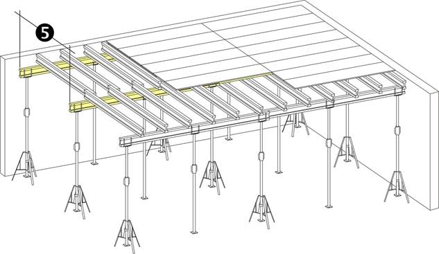
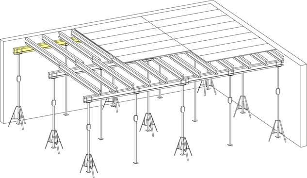
❺ Primary beam spacing L
Maximum deflection of the boarding support beam: L/500 for loading in
acc. with EN 12812.
The maximum possible primary beam spacing is determined from the deck
thickness and the boarding support beam spacing. The maximum permissible
boarding support beam spacing a must not be exceeded.
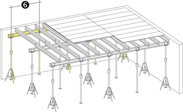
❻ Prop spacing SR for edge
primary beam
Deflection of the primary beam maximum S/500 for loading in acc. with EN
12812. The maximum possible edge prop spacing is determined from the deck
thickness, boarding support beam spacing, primary beam spacing and edge span
length. The maximum permissible boarding support beam spacing a and primary
beam spacing L must not be exceeded.
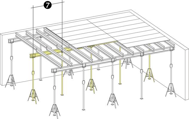
❼ Prop spacing SM for
intermediate primary beams
Deflection of the primary beam maximum S/500 for loading in acc. with EN
12812. The maximum possible intermediate prop spacing is determined by the deck
thickness, boarding support beam spacing and primary beam spacing. The maximum
permissible boarding support beam spacing a and primary beam spacing L must not
be exceeded.